
Well Chokes
Well Chokes in PetroVR
A production well is said to be choked at a given step of the simulation when because of constraints in the routing of fluids it cannot deliver its full potential production, as determined by its decline curve. In other words, the system of facilities directly or indirectly connected to it cannot accept this potential production, because of capacity limits, deliverability limits or downtime, and therefore scales back part of all of the incoming fluids.
Chokes are applied automatically at each step of the simulation as a result of calculating the potential production of every well in the system, and the constraints found at all points of the routing line; in this sense, they can be regarded as the system's reaction to current pressure conditions. Since they instantaneously remove the difference between potential production and system capacity, they last for just one step, and the whole system will be evaluated again at the beginning of the next step.
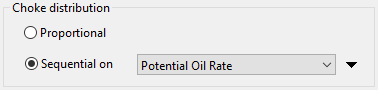
The Choke distribution pane in the Excess Policy Tab allows you to define the policy to be applied when choking wells directly or indirectly feeding this facility. You can choose between choking all wells proportionally at the same time, or according to a pre-defined sequence.
Keep in mind that in principle choke options apply not to wells but to each incoming connection as a whole, whether it originates in a well manifold or another facility. This means that each incoming connection will in turn re-distribute the choke among its feeders. If it is a manifold, it will choke all its wells proportionally, regardless of the selected policy. If it is another facility, it will apply its own predefined choking policy.
However, if a facility has only (a manifold of) wells feeding it, and a sequential choking policy is applied, the wells will be choked sequentially.
The options are:
- proportional: Choke each incoming connection proportionally to its contribution to the facility total potential production, so that:
Connection Choke = Total Excess * Connection Potential / Total Potential
- sequential: Specify the sequence in which incoming connections should be choked; in this way, each one will be completely shut in if necessary before the next one in the list is choked. The following sequencing criteria are available:
- User-Defined Sequence: Use the Edit sequence command to set a precedence order of connections feeding this facility. Connections upper in the list will be choked first.
- Potential Oil Rate: Manifolds and facilities will be choked first depending on their oil rate.
- Potential Gas Rate: Manifolds and facilities will be choked first depending on their gas rate.
- Potential Water Rate: Manifolds and facilities will be choked first depending on their water rate.
- Water Cut: Manifolds and facilities will be choked first depending on their water cut.
- GOR: Manifolds and facilities will be choked first depending on their GOR.
- <component / main fluid> Ratio: Manifolds and facilities will be choked first depending on the ratio between a component defined in the Fluids Tab and the main fluid; e.g. "C (carbonate) / Oil Ratio".
- WI: Working Interest defined for the main partner in Contracts.
- NI: Net Interest defined for the main partner in Contracts.
- NI/WI: Ratio between Net Interest and Working Interest for the main partner in Contracts.
Use the  button to choose between ascending and descending order.
Well choking order can be modified by activating the option to Choke wells in this reservoir/group only as last resort in some types of groups (see Well Groups) or in the reservoir Details Tab (Reservoir), or by enabling the Ensured oil/gas/water rate option in Manifold Groups. Wells for which these options have been enabled will be prevented from being partially or totally choked until there are no other active wells; after that point, they all will be choked proportionally.
Keep in mind that a facility's processing capacity is evaluated separately for each fluid (oil, gas or water) and component, and any of these may cause an excess state. In this case, all wells that contribute at least a percentage of the fluid in excess will have all their fluids scaled back, since these fluids come naturally in a three-phase that is not separated before reaching the facility. Therefore, when defining capacities care must be taken to account for the routing of all involved fluids.
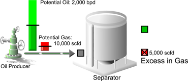
In the example above, Separator has a max gas capacity of 5,000 scfd, and the potential gas of Oil Producer is 10,000 scfd. Half of it is scaled back, but since all fluids have to be scaled back proportionally, the oil production of 2,000 bpd is curtailed to 1,000 bpd too.
The sequential choke option cannot be used concurrently with Downtime Simulationon the same facility or on facilities processing fluids from the same reservoir. This is due to the different logic applied by these two features for the calculation of constraints.
When because of a choke policy a well's production tends to decrease in such a way as to remain close to its economic limit without ever reaching it, PetroVR forces a cancellation of the choke in order to allow the well to reach its limit and be abandoned in time. This may be reflected in an unexpected production peak at the last reporting period in the corresponding graph.